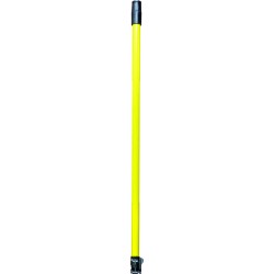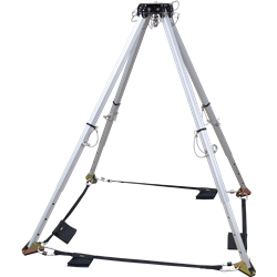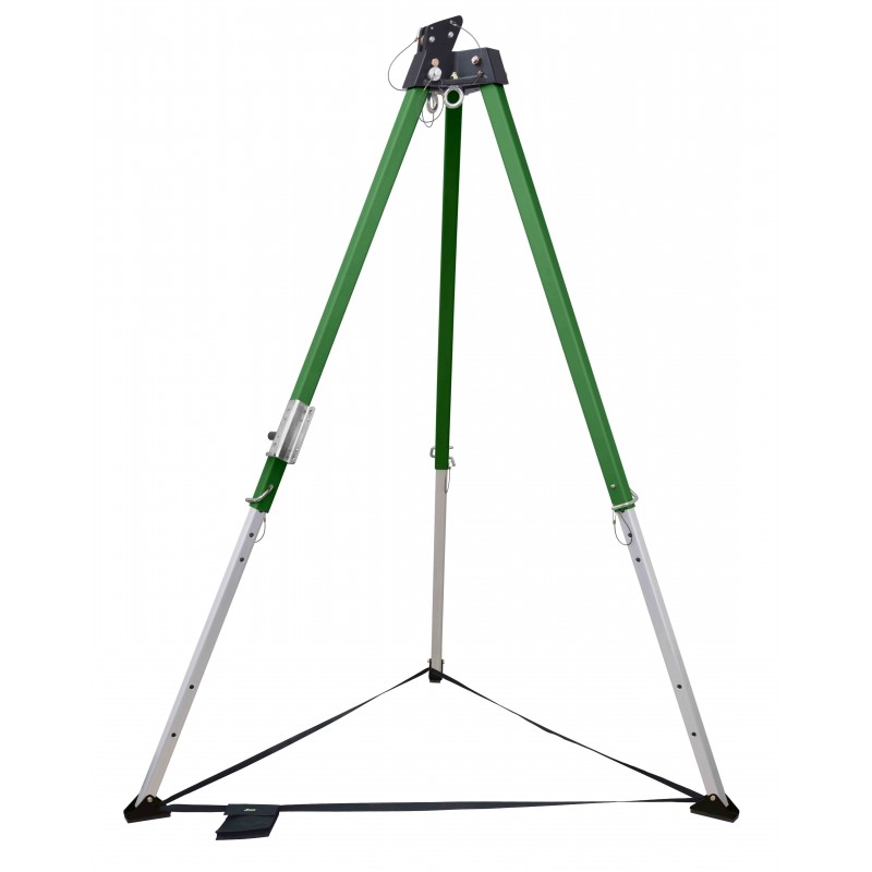
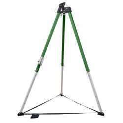


Tripod with 10 feet height maxi for access in confined spaces

10 ft. Tripod
For access in confined spaces
Adjustable height : from 1.9 m to 2.9 m
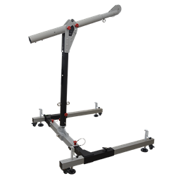
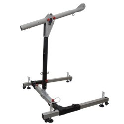
Wheelbase :from 1.52 m to 2.05m
Weight :22.3 kg
Maximum Load Capacity : 500 kg under head / 250 kg on leg
Conforms to : EN795:2012 type B, ATEX Directive 2014/34/EU, Machinery Directive, EN 1808.
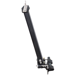
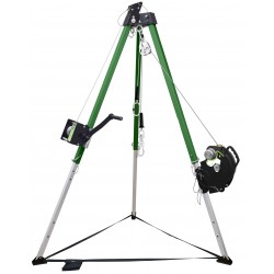
- With two mini pulleys mounted at the head of the Tripod in the extension of the main leg for passing a cable
- Having two auxiliary eye bolts as attachment points below tripod head.
- Aluminum alloy cast head, legs in aluminium.
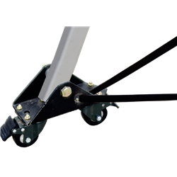
- Steel support-shoes provided with rubber sole to increase friction and impart more stability.
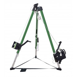
- Strength of anchorage point greater than 12 kN
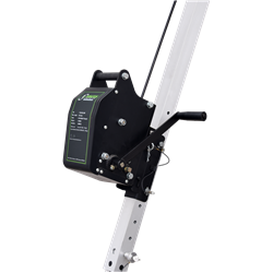
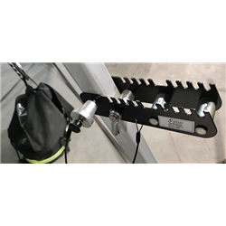
- Every Tripod is provided with inbuilt fixture for attaching our winches FA 60 003 20/20S / FA 60 003 30/30S.
- Every Tripod is provided with Tripod Bag.
To download the Tripod instructions for use, see the Attachment tab
![]()
Tripod with 10 feet height maxi for access in confined spaces